
Outdoor transformer yards look open and forgiving, yet a single failure can escalate in seconds. Hot oil release, arcing, and sustained radiant heat can ignite nearby equipment, damage control cabling, and threaten personnel access routes. Wind can push flames and smoke sideways, while debris and shrapnel can turn a localized event into a yard-wide outage. Intumescent barrier systems are designed to slow that chain reaction by shielding assets, controlling heat transfer, and buying time for isolation and response. When they are specified correctly, they reduce the probability that one transformer incident becomes multiple incidents, while supporting safer operations during emergency conditions.
How barriers change the incident timeline
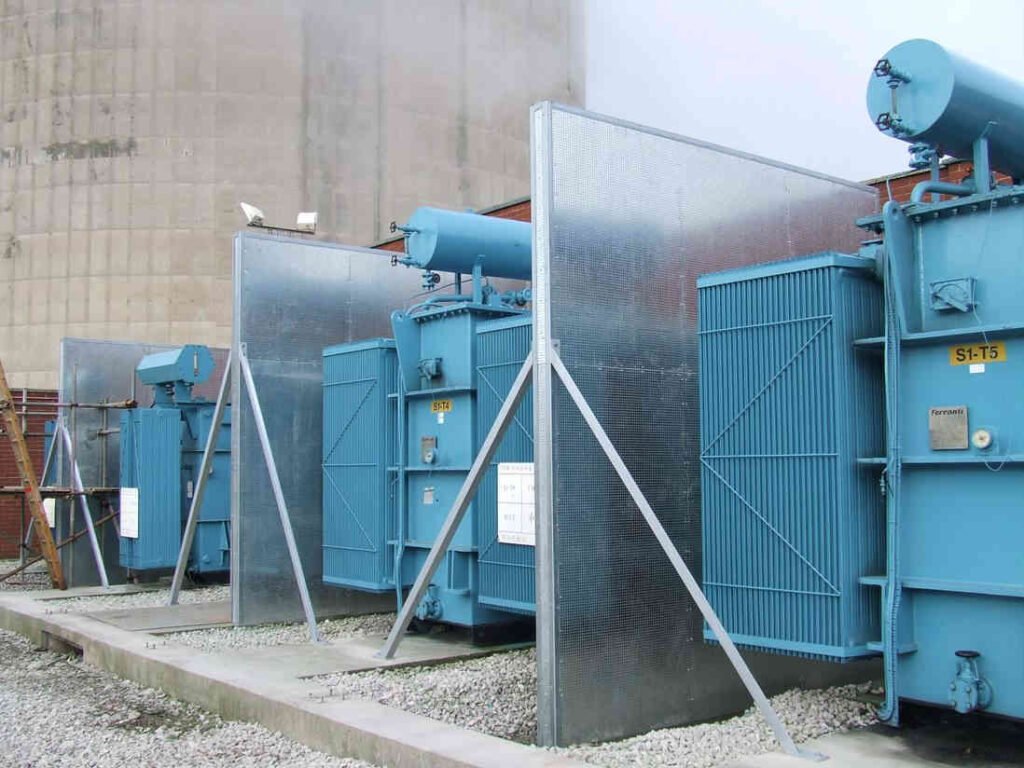
- Why intumescent barriers fit yard realities
Outdoor yards demand solutions that tolerate UV exposure, rain, freeze-thaw cycles, and constant thermal cycling from the sun and equipment heat. Intumescent systems address these realities by staying thin and stable in normal conditions, then expanding when exposed to fire. That expansion creates an insulating char layer that slows heat transmission, reducing radiant heat impact on adjacent transformers, cable trays, and structural steel. The goal is not to make the yard fireproof; it is to keep temperatures on protected surfaces below critical thresholds long enough for protective relays to isolate the fault and for responders to act without immediate secondary ignition. Placement matters as much as material. Barriers can be configured as freestanding panels, wraps for structural elements, or protection around vulnerable interfaces such as control cabinets and conduit transitions. In yards with tight spacing, intumescent assemblies can also help reduce the need for wide separation distances, provided the design aligns with the facility risk model and local requirements. The result is a more predictable fire progression instead of a rapidly compounding event.
- Integrating blast, fragment, and thermal protection
Transformer failures can produce more than flame. Pressure events may create fragments, oil spray, and shock effects that stress nearby equipment and barrier supports. A credible design considers mechanical loads first, then layers in thermal performance. That means anchoring to foundations that can resist wind and impact forces, selecting framing that will not buckle early, and ensuring joints do not become weak points under heat. Intumescent layers can be paired with robust facing materials that withstand weather and incidental contact, while still allowing the fire-driven expansion to occur. Drainage and yard grading should also be considered, because oil migration can carry fire under or around barriers if containment and flow paths are ignored. In many projects, barrier strategy is blended: thermal shielding to reduce radiant exposure, deflection or capture to manage fragments, and geometry that discourages flame impingement on adjacent assets. For teams evaluating combined protection approaches, https://firebarrierexperts.com/ballistic-barrier/ can be referenced when considering barrier concepts that address both impact and fire-driven hazards in high-energy failure scenarios. A unified approach prevents solving one threat while leaving another to drive escalation.
- Details that decide whether protection holds
The difference between a barrier that performs and one that disappoints is usually in the interfaces. Gaps at the base, unprotected penetrations, and poorly sealed seams can become heat funnels that bypass the intended shield. Outdoor transformer yards also present constant movement: thermal expansion, vibration, maintenance traffic, and occasional minor impacts from equipment handling. If the system is not engineered for those realities, cracks, foaming, and water intrusion can degrade performance over time. Good designs include robust edge detailing, weather-resistant caps, and an inspection access point that allows the crew to verify integrity without dismantling the system. Another deciding factor is clearances. Barriers must not interfere with required electrical approach distances, ventilation needs, or egress routes, and they must support safe switching and maintenance operations. Maintenance planning should be part of the initial specification, including how coatings are repaired, how panels are cleaned, and how damage is documented. When barriers are treated as a living asset with periodic checks, they keep their performance assumptions intact instead of becoming a forgotten structure that only gets attention after an incident.
Commissioning and long-term verification
Barrier systems should be commissioned with the same seriousness as protective relays or containment hardware. Verification starts by confirming that the installed geometry matches the hazard model: sightlines of radiant exposure, likely oil-spray paths, and the assets whose loss would result in the highest outage consequence. Documentation should include material data, installation photos, and clear inspection criteria so future teams understand what normal looks like. Periodic reviews can be scheduled around seasonal changes and major maintenance outages, focusing on corrosion, UV wear, fastener integrity, seam condition, and ground clearance. It also helps to coordinate with emergency response planning. Barriers can change how responders approach the scene, where they stage, and which isolation steps they prioritize. When those operational realities are aligned, the barrier becomes part of a practical response timeline rather than a passive object. In the long run, the value of intumescent barrier systems is measured in avoided escalation: fewer damaged adjacent units, less smoke and heat exposure to controls, and a higher likelihood that a single failure stays contained to a single asset zone, even under wind and weather conditions that typically worsen outdoor fire behavior.