
There is a type of engineering excellence that is specifically invisible by design. It doesn’t announce itself with bold geometry or striking material choices. It achieves its goal precisely by disappearing — by leaving no evidence of its presence except the function it enables. The flush-mounted fastener in a finished sheet metal surface is this kind of achievement: a threaded insert that creates a loadbearing attachment point without producing any projection above the material plane, preserving the surface continuity that the designer intended and the mating surfaces that follow in the assembly depend on.
Getting this right requires navigating a specific set of engineering constraints that do not appear in any simplified version of the fastener selection conversation — and understanding them clarifies why head profile geometry in blind fastener selection is not a cosmetic choice but a functional one.
What happens at the surface when a fastener head sits proud.
In the simplest terms, a fastener head that projects above the surface of a panel creates a discontinuity. In applications where that surface will be mated to another panel, covered by a finished trim element, or installed flush against a frame or structure, any projection interferes with the intended geometry of the assembly. The mating surface either cannot seat correctly, produces a visible gap at the joint, creates a stress concentration where contact is made at the fastener head rather than distributed across the full mating surface, or requires machining or shimming to accommodate the protrusion.
In sheet metal assemblies — electronic enclosures, HVAC panels, automotive interior components, commercial equipment housings — the consequence of a proud fastener head ranges from cosmetic compromise to functional assembly failure. The tolerance stack across a multi-panel assembly that relies on all mating surfaces being flat is tight, and a fastener head projecting even a millimeter above the panel surface can prevent correct assembly of adjacent components.
Why the flat head geometry serves different needs from the countersunk.
The fastener specification community sometimes uses “flush” and “flat head” interchangeably, but they describe geometrically distinct solutions to the projection problem.
A countersunk head fastener — whether a screw or a rivet nut — achieves flush installation by sitting in a conical recess machined or formed into the base material. The head’s conical geometry matches the countersink angle, and the fastener seats with its top face level with or slightly below the material surface. This is a true flush condition, but it requires the additional manufacturing operation of creating the countersink — a step that adds cost, requires tooling, and can create problems in thin materials where countersinking removes a significant proportion of the wall thickness.
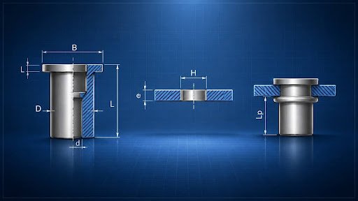
A flat head fastener achieves a different objective: it provides a large, flat bearing surface on the face of the material without the depth of a countersunk profile. The Bollhoff RIVNUT® flat head round body design provides a wide bearing flange that distributes clamping load across a larger surface area on the front face of the panel, reducing the stress concentration at the fastener location while keeping the installed profile as low as possible.
The flat head rivet nut is the correct selection when theinstallation surface must remain substantially flat — when projection cannot be tolerated because of mating surface, aesthetic, or clearance requirements — but the additional manufacturing step of countersinking is not available or practical. The flat head bears against the surface, the barrel extends through the hole, and the bulge formed on the back of the panel during installation provides the retention. The front face presents a low, flat profile that minimizes interference with whatever follows in the assembly sequence.
The relationship between head diameter and bearing area — and why it matters.
One of the underappreciated details of flat head fastener selection is the relationship between head diameter and the bearing area it provides. A larger head diameter distributes the installation clamping force over a greater area of the panel surface, reducing the peak stress at the fastener location. This matters specifically in applications where the base material is thin, soft, or where repeated removal and re-installation cycles will stress the fastener seat.
In thin-gauge aluminum or steel, a small-diameter fastener head concentrates the bearing load on a limited area of material that may have insufficient bearing strength to resist deformation under full installation torque. Deformation of the material at the fastener seat introduces inconsistency in the installed height — the head settles into the surface rather than bearing cleanly against it — which can compromise both the flush condition and the pre-load achieved at installation.
Selecting a flat head profile with adequate head diameter for the base material’s bearing strength is the dimension of this decision that most simplified fastener selection guidance doesn’t address. The catalog specifies the fastener; the engineer must match the head diameter to the material’s ability to carry the bearing stress without deformation.
The open-end versus closed-end distinction and why it matters in sealed assemblies.
Within the flat head round body category, the distinction between open-end and closed-end configurations addresses a different requirement entirely. The open-end RIVNUT® allows a bolt or screw to pass completely through the fastener after installation — which is appropriate when the attachment bolt’s length extends beyond the fastener body. The closed-end variant provides a sealed base that prevents fluid, debris, or gases from passing through the fastener hole — a requirement in sealed enclosures, fluid-containing structures, or environments where contamination control is required.
This choice is invisible from the front face of the installed fastener but consequential for the assembly’s function. An open-end fastener installed in a panel that is later expected to seal against fluid ingress fails the sealing requirement regardless of gaskets or sealants applied at the panel joint — because the penetration through the fastener body itself provides a fluid path. The correct fastener for a sealed application must be specified from the beginning; it cannot be retrofitted after the decision has been made.
Why the invisible fastener reveals the sophistication of the engineer who selected it.
The finished sheet metal assembly that presents a smooth, uninterrupted surface — with no visible fastener heads, no surface protrusions, no evidence of how the panels are held together — is the output of dozens of fastener selection decisions made correctly. Each of those decisions involved understanding what the surface required, what the material could support, what the mating parts downstream of the fastener location expected, and which head geometry, body type, and end configuration satisfied all of those requirements simultaneously.
None of that decision-making is visible in the finished product. It shows only in what is absent: the gaps that didn’t form, the surfaces that mated correctly, the assembly that functions exactly as designed. The invisible fastener is the product of visible engineering intelligence — applied precisely to a problem that, when solved well, leaves no trace of having been a problem at all.